Power Prediction Program
Power Prediction Program (Version 3)
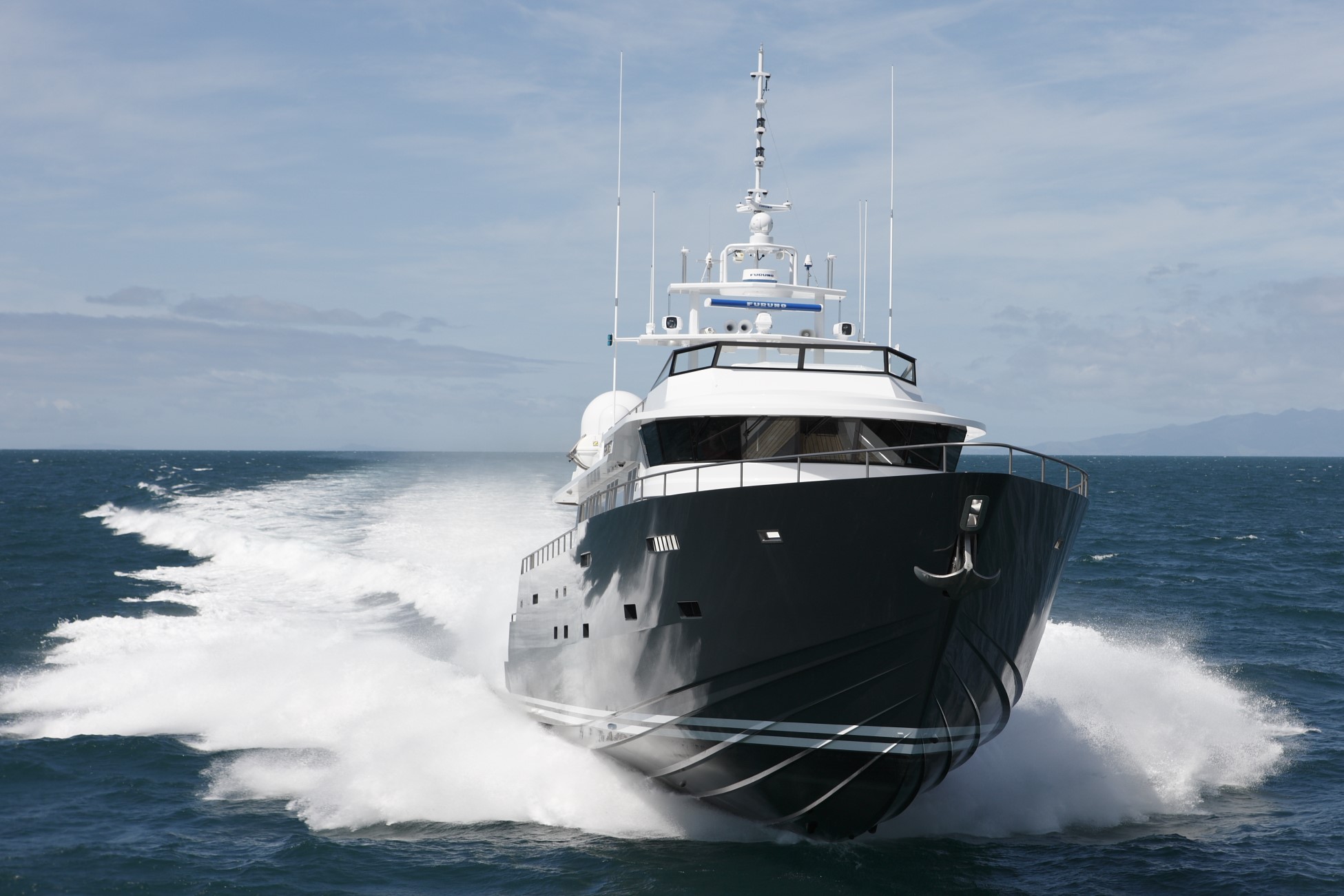
The Power prediction program calculates the powering requirements of vessels covering a large range of hull forms from merchant ships to planing vessels, using a variety of analytical and regression methods.
The program can calculate the added resistance of appendages and the effect of changes in hull form parameters. In addition to calculating the resistance and EHP, the program also calculates the propulsive coefficients at each speed for direction input into the Propeller Design Program. The Power Prediction Program offers standard calculation methods e.g. SSPA and Savitsky, and four Wolfson Unit series:
- Wolfson Unit Round Bilge,
- Wolfson Unit Catamaran Craft,
- Wolfson Unit High Speed Craft,
- Wolfson Unit Round Bilge Megayacht.
The Wolfson Unit series have been obtained by regressing trim-optimized data from 50+ years of towing tank tests performed by the Wolfson Unit.
£1230

Propeller Design Program
Propeller Design Program
The Propeller design program computes propeller performance from standard Gawn and Wageningen B-series propeller charts or propeller data input by the user. Data for Kaplan propellers operating in nozzles are also provided.
The program provides a rapid means of determining the optimum propeller parameters (diameter, pitch, blade area ratio etc) or allows investigation of the influence on performance and efficiency of various design parameters. The program also allows the user to check for the onset of cavitation.
£870

How to order
- Purchase via the Wolfson Unit Online Store.
- Confirmation of payment is automatically emailed to you.
- Hardware lock (USB dongle) and installation instructions are couriered to you.
- The latest version of the software and release notes can be downloaded from the customer download area.
Need a quotation or require an invoice to purchase? Please contact us.
Frequently Asked Questions (FAQs)
FAQs
The software manuals and help sections should be enough to master the software but to help with some more complex processes there are some frequently asked questions listed below:
Power Prediction Program
When using the Wolfson Catamaran model, is Base Data for the entire vessel or one demi-hull?
The base data is for one demi-hull, you can check your input by placing the cursor over the relevant input box and its description is displayed in the lower left corner of the program page.
How do I know exactly what to input into the entry fields?
Hover the mouse pointer over the entry field and details of the required input will appear at the bottom left hand corner of the program window.
How does the input propeller shaft angle in the Wolfson Unit methods (11, 12, 13, 14) affect the prediction of EHP/Resistance?
It doesn’t. The only influence that the shaft angle will have is in the prediction of propeller coefficients for use in propeller design calculations. If you want to make the program run and aren’t interested in the propeller coefficients then just enter a value between 7 and 14 degrees
Propeller Design Program
My propellers are for a 13″ diameter duct. The Kaplan data lists the series as 19, 24 and 37. Can the data be used on smaller propellers?
The nomenclature of the propeller files in the nozzle series is as follows:
- A – Kaplan blades have square tips that run just inside the inner surface of a nozzle, thus reducing tip losses (as in bow thrusters blades). B-series blades have the normal rounded tips of propellers in open flow, but can be run inside a nozzle, this is usually a retrofit as they don’t get the advantage of reduced tip loss.
- B – Four different nozzle types were tested these are designated as 19a, 22a, 24a, and 37a. 19a is the most common, used for tugs and fishing boats with heavily loaded propellers, fishing boats also get the advantage of having a guarded propeller to reduce fouling of lines, 37a is also used for tugs that need to use reverse thrust a lot. The number does not signify a size, but a shape.
- C – Number of blades is obvious.
- D – BAR is the blade area ratio, e.g. 0.65 means the developed blade area takes up 65% of the disc (less hub) area.
In the KT-KQ-J charts, all of the data is dimensionless, with most test propellers in the region of 4″-6″ diameter for example, and run at high revs so increasing Reynolds numbers to reasonable levels. We would be happy to recommend the program to design props at any size between 3” and 10 metres diameter.
Can you provide further information upon nozzle / duct shaping?
A number of differing nozzle designs have been developed by MARIN (MArine Research Institute, Netherlands) for unique thrust characteristics. MARIN Nozzle No. 37 has a rather thick trailing edge, while MARIN Nozzle No. 19A was crafted with a thinner trailing edge. Nos. 22 and 24 were designed with larger length-diameter ratios (0.8 and 1, respectively). Although all four of these nozzle types present a large improvement over a non-ducted propeller, the differences between them are relatively small and refined. Nozzles No. 19A, 22, and 24 are somewhat more efficient than No. 37.
Help and support
If you need any support from our team for the effective use of our software, please get in touch.