Description
HullScant is designed for builders and designers performing scantling assessments, streamlining the design category evaluation process for pleasure craft under the Recreational Craft Directive. Used world wide by designers, structural engineers, regulatory bodies, and industry professionals, it simplifies compliance with the latest ISO 12215 standard.
The software calculates a vessel’s scantling structural properties and compares them with the standard’s requirements, including all published errata. It covers pressure and scantling equations for fibre-reinforced plastic, metal, and wood boats up to 24m in length.
Feature List:
- 3D IGES file import for hull specification and structural elements.
- Extensive materials library from ISO standard or imported manufacturers data
- Laminate stack analysis for panels and stiffeners.
- Stiffeners library including: L, T, bar, top hat and wood shaped.
- Annex J (workboat) included.
- Design variations (e.g. displacement or design speed) calculated
- Actual structural properties of the vessel are calculated.
- Structural requirements from ISO standards are also calculated.
- Pass/fail comparisons to the standards are made.
- Results presented as HTML, PDF or as CSV file
- Regular updates due to published ISO errata and user feedback.
Purchase Options
Monohull and multihull licences are purchased individually. The second licence (i.e. multihull if the monohull licence is bought first, or visa versa) can be purchased at a reduced rate.
The rudder module, when available, will be an add-in and will not operate on its own without a mono or multihull base licence.
HullScant Monohull
HullScant Monohull
The Monohull version of HullScant analyses the structural designs for sailing and motor monohulls and then compares to ISO 12215-5:2019, including all errata published to date.
£1610
HullScant Multihull
HullScant Multihull
This HullScant licence is limited to multihull designs and therefore compares the structural design to the requirements in part 7 of the standard, ISO 12215-7:2020, including all errata published to date.
£1610
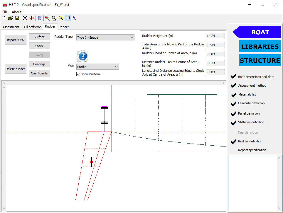
HullScant Rudder
HullScant Rudder
This module extends HullScant’s functionality so that the structural designs for rudders on vessels under 24m. Their structural properties are calculated and compared to ISO 12215-8:2009, including all errata published to date.
Description
- Both spade and all types of skeg-hung rudders can be assessed.
- The offered rudder structure is compared to the requirement of ISO 12215-8:2009 , and a pass ratio is calculated for stock size, bending moment and torque as appropriate for the rudder type and construction.
Key Features
- IGES import allows easy definition of the bodies (rudder blade, stock and skeg), with internal calculations of moments of area and geometrical properties.
- User defined values of principal dimensions and data allows quick calculations and sizing without a full CAD definition.
- Hullscant’s material and laminate libraries allow quick and easy structural property specifications , leveraging the laminate stack analysis already embedded in Hullscant.
- Results are presented in either an HTML or PDF report.
- Hullscant rudder incorporates ISO 12215-8:2009 , sections 5-10, 12.2, and 13-14, but not 11 or 12.1.
£500
How to order
- Purchase via the Wolfson Unit Online Store.
- Confirmation of payment is automatically emailed to you.
- Hardware lock (USB dongle) and installation instructions are couriered to you.
- The latest version of the software and release notes can be downloaded from the customer download area.
Need a quotation or require an invoice to purchase? Please contact us.
Frequently Asked Questions (FAQs)
FAQs
The software manual and help section should provide sufficient information to master the software. In addition a few complex processes are explained below. Answers beginning with R1 are relevant to HullScant Release 1 and the ‘old’ ISO standard 12215-5:2008/AMD 1:2014 ONLY. Answers beginning with R2 are relevant to HullScant Release 2 and the current ISO standard 12215-5:2019 ONLY . A number of answers are relevant to both Hullscant R1 and Hullscant R2
General HullScant and ISO 12215 Standard questions
Can you please list the differences between HullScant R1 and HullScant R2
At the most basic level, HullScant R2 assesses against ISO12215-5:2019 whereas HullScant R1 assesses against 12215-5:2008 (inc A1 2014). The differences between the standards are significant, hence it isn’t really possible to list the individual changes to the standard. In addition to the change to the standard, HullScant R2 has a significantly changed user interface and increased geometry import functionality (IGES files of hullform and individual structural components can be read in), and a number of structure inputs (eg local deck height, panel height above DWL) are automatically calculated by the program.
As HullScant is based on the ISO standard and the ‘design categories’ I presume that the pressures it calculates are based on the maximum wave heights for those categories. Does this mean that if I enter a speed of 25 knots for Category B the pressures are based on 4m waves at that speed, or does it appreciate the vessel cannot be driven at that speed in that sea state ?
R1 > When writing HullScant the Wolfson Unit used the standard that is created by ISO working group 18, we do not write this standard. We understand there is an inherent consideration of reducing speed in waves – section 3.1 of the standard describes this –and there is consideration of this fact in the design pressure for certain types of vessel (e.g. see the Notes in section 8.1). If you would like a full and comprehensive technical answer to this question it would be best placed to the convener of the ISO working group. HullScant is an assessment of the provided particulars against the ISO 12215 standard, NOT an assessment of the vessels suitability for a specific environment.
R2 > There is an explicit listing for speed reduction of workboats in waves in Appendix J of the ISo 12215-5:2019 standard
Have you ever thought about producing a more general software without the ISO limits? That is, have you considered adding an option into HullScant to add design pressure directly – say a design load on deck or the load from a block? This could be called ‘user load’ with direct input of design pressure. The material and laminate stack build could be the same, but without the ISO limits while calculating the characteristics of a ply or stack, and instead the general theory can be used.
R1 > HullScant will never be able to go outside the ISO limits as this has never been validated and could lead to many user errors. In terms of your suggestions this may be difficult as there are intrinsic safety factors in the material properties etc. that are then accounted for in the ISO 12215 prediction of loading and pressure. One cannot work without the other. However, the user is able to obtain the stiffener and laminate strengths in the program without doing a full ISO calculation using the Results, Stiffer Properties or Results, Laminate properties menu items respectively. All in all, the software should not be considered to be a design tool; it checks conformity to the ISO standard, which in turn is a ‘sizing rule’. i.e. no part of the standard should be used in isolation.
R2 > While the above answer is still valid with respect to adherance to standards and intrinsic interaction of safety factors and design pressures, Hullscant R2 allows the user to specifiy their own design pressure in the Plating dialog. If this is enacted, the report clearly denotes that the results are not ISO compliant. It should also be said that the use of this feature and its implications are very much at the users discretion and responsibility.
What version of the ISO 12215 standard is used in the software ?
R1 > The program is in accordance with the April 2008 publication (2008-04-15) of 12215 part 5. We have released updates after every version change of the standard, free of charge to existing customers. The version of the standard used within a given version of HullScant is listed in the Report section, as well as the About screen. If you need to update your existing copy, please go to our Customer Download Area.
R2 > The program is in accordance with the December 2023 ISO publication (2023-12-31) of 12215-5:2019 and some of the errata published by WG 18 up to and including 2023-12-31 . We have released updates after every version change of the standard, free of charge to existing customers. The version of the standard used within a given version of HullScant is listed in the Report section, as well as the About screen. If you need to update your existing copy, please go to our Customer Download Area.
What errata are incorporated in the software ?
Hullscant, as of 2024-02-22, uses ISO on ERRATA items 4.6, 4.8 and 4.28, but incorporates ERRATA items 4.14, 4.16 and 4.22.
In more depth, comparing the 2023-12-31 standard (ISO) versus the 2023-12-31 errata (ERRATA) , the differences that affect hullscant are –
ERRATA items :
4.6 Design area ERRATA has a limit of 2.5 b^2 . ISO has no limit on panel area .
4.8 ERRATA uses a limit of 3Lh^3 ISO has a limit of 5 Lwl^3
4.14 & 4.22 (the same point, but said in 2 different ways) . Min core properties
- ERRATA : Sigma DCCO >= 0.004 P base
- ISO : Sigma DCCO >= 0.008 P base
- ERRATA : Tau DCCO >= min ( max( 0.055Lh – 0.03 , 0.3 ), 0.52 )
- ISO : Tau DCCO >= min ( max( 0.07 Lwl – 0.12 , 0.3 ), 0.58 )
4.16 ERRATA use a blend of K shb from 2008 and 2019 standards
4.28 ISO uses flexural stress, ERRATA uses tensile and compressive
4.31 poisson ratio for CSM ; std say E/G -1 ERRATA say E/((2G-1) .
There are a few other ERRATA differences from ISO (eg Al material properties , table B1 & B2).
Commentry :
4.16 – This was developed by industry professionals as their opinion was that ISO 2019 was overly penalising certain aspect ratios and curvatures.
4.14/4.22 – It is generally felt by the industry that the standard was overly conservative and effectively disallowed successful designs.
4.31: Both wrong : should be (E/2G) -1 by std theory , and that matches data in table C6 . Not actually used in anger in any formula inside Hullscant.
Hullscant, as of 2024-03-22, uses ISO on ERRATA items 4.6, 4.8 and 4.28, but incorporates ERRATA items 4.14, 4.16 and 4.22. The errata command (File menu) allows the user to switch between the errata and the published standard on each of these items.
Is the program verified by a third party ?
R1 & R2 > The program has not gone through an official third party verification process and certification but R1 was endorsed by both the RYA (a Notified Body) and ISAF while R2 is used by an extensive number of notified bodies.
Does HullScant cover multihulls?
R1 > No, HullScant currently only covers monohulls, as per Part 5 of the ISO 12215 standard. Part 7 of the ISO 12215 standard is currently (June 2009) deleted, and hence there is no standard upon which to base the software.
R2 > The base module of HullScant only covers monohulls, but ISO 12215-7:2020 (multihulls) is due to be released as a additional module in the first half of 2024
Whats the second module?
Hullscant release 2 (Hullscant R2) was released in 2021, and at that point assessed against ISO 12215-5:2019 (ie the re-written standard covering monohulls) only. A second module , assessing against 12215-7:2020 (multihulls), was released in 2024. In 2025 assessment of rudders (ISO 12215-8:2008, all types) was added to Hullscant R2, for either or both monohulls or multihulls, depending on which modules are active.
Hullscant R2 can currently be initially bought to cover either monohulls or multihulls . The second module (multihull if monohull already purchased OR monohull if multihull already purchased) can be added as and when required by the user. The rudder module can equally be added at any point (but can not be the initial module purchased), and assesses for monohull or multihull specifications as necessary.
Are the outboard motor forces in Annex K incorporated into the panel scantlings?
R2 > No, they are purely informative and are not incorporated into the requirements / pass ratio in the main report. The origins of these formulae are in a VTT report (https://cdnmedia.eurofins.com/european-east/media/2847843/guidelines-for…), section 7.12, page 105.
Can you assess a vessel as a workboat, as per Annex J?
R2 > Yes, just check the box in the ‘Assessement’ tabsheet and select the appropriate work boat type. The user can also select up to 12 different wave heights for speed reduction.
What happened to the ‘user design pressures’ checkbox on the Assessment tabsheet ? Its disappeared.
R2> This option is now on the ‘Design Variations’ dialog, which can be accessed via the button on the Assessment tabsheet. There were beginning to be too many options for the one control panel.
Geometry Import
General notes about IGES import
HullScant imports IGES from most source CAD packages with little issues. Occasionally there are a few odd import issues, in which case please contact the Wolfson Unit. Packages that have been confirmed to import properly include Rhino, Solidworks, MaxSurf, and CATIA. A few key points to remember are –
IGES files can be imported as one of three items-
- hull definition import – surface & curves used
- panel import – surface read only
- stiffener import – curves read only
These three do not link to each other; hull definition is used to determine the vessel size and required data such as the deck edge height (via the sheer line) which panel definition and stiffener definition is used to define the size, curvature and location of the structural element to be assessed.
Individual surfaces are read as panels, and individual curves as stiffeners. That is, if you import the whole topside as one surface, it will be read as one (very large) panel. The user needs to split the surface into smaller surfaces, each one representing a panel as defined by the ISO standard.
HullScant primarily reads NURBS surfaces, and prefers type 143 to 144; if data is not being transferred very well check what it is being exported as, and if the option is there, choose Type 143 trimmed NURBS surfaces.
HullScant reads (and converts) according to the units listed in the IGES header. If the user has drawn the vessel in metres, but the CAD package is set to millimetres then the vessel will be scaled on import; check the unit setting in the CAD package !
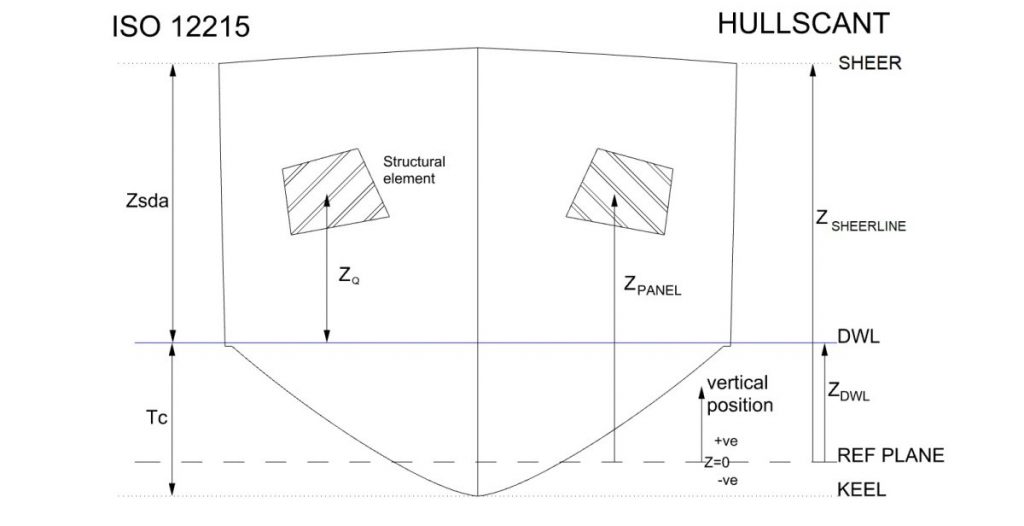
Ensure you have the vessel in the correct orientation (X longitudinal, Y transverse, Z vertical). X =0 at aft end of waterline and +ve towards the bow. Z vertical upwards. The ISO standard has z=0 at DWL; Hullscant allows for a different vertical datum with the user specifying either draught or offset of DWl from the datum on the Assessment tab.
It is also worth reading (if you haven’t already) the ‘General Order of Working’ page in the Process Description section of the help files installed with the program ( ‘About’ pull down menu ->’Help’). There is also a simple ‘getting started’ guide available for download as well as a document discussing the different geometry requirements for multihulls , if that module is active and being used .
It is generally a good idea to import sets of panels (or stiffeners) together; for example save (and then import) all bottom panels in one IGES file, and all topside panels in one file. It is not essential to do this, but makes import, data management and tracking of issues much easier.
IGES import of stiffeners is not working
R2> HullScant only reads curves when importing stiffeners, NOT surfaces. That is it reads the ‘footprint’ of the stiffener on the hull surface, extracting length and curvature. The stiffener library allows the user to create the stiffener shape. Stiffener spacing has to be specified by the user currently.
What’s the best way of importing geometry, especially sheerline definition?
The ISO 12215-5 standard requires the height of the deck edge (ie the sheer line) and , where required, the chine line.for monohulls. ISO 12215-7 requires the height of a considerable more entities (float deck edge, keel line, wetdeck line, hull-wetdeck join etc etc).
To explain the concepts involved, a monohull shall be described first , after which the extensions required for multihulls will be described.
Monohull / main hull
The solution utilised in HullScant is to define a number of transverse sections along the length of the vessel (ie stations in naval architecture nomenclature). There are 21 stations (stations 0-10 at half station gaps, each of which are defined by a set of points defining the shape of the hull. From the points that define these stations, specific ones are chosen to define the hull lines (keel line, sheer line etc) along the length of the vessel.
There are several approaches that can be used to define these station curves and hull lines; the easiest way is via importing IGES file(s).
- The station curves can be defined by importing a set of IGES surfaces. Hullscant will calculate the extentd and then extract the curves and points at each station. If the IGES file also contains curves with specific names (see the relevant glossay {linkID=700}entries for these names), then the keelline, sheerline etc will be defined by these lines. If the IGES file does NOT have curves with these specific names, then Hullscant will attempt to define the keel and sheer from the imported shape. Which ever approach is used, the hull line (keel line etc) can be editted{linkID=*440} at a later point.
- Import the keel line, sheerline etc one by one via the edit pull down menu. Import an IGES file consisting of points, lines and NURBS curves. surfaces will be ignored if this method of import is used.
- As with method above, click on ‘Add keel line’ (or equivalent) in the Edit pull down menu but when asked where the data is to come from, click on ‘By Hand’. Hullscant will create a best guess of the line, depending on what information is available (station curves, just hull dimensions etc etc). The user can then edit these values before accepting. As with the other methods, the curve can be editted at a later point.
It should be noted that there is not a current method for adding more points to a station curve other than adding an IGES file, hence using the ‘by hand’ approach has a minimal number of points defining the station. This is not a problem for the ISO standard calculations, but visually is limited and can be difficult if the points need to be extensively moved.
Mutlihulls
Multihulls have the need for addition curves, specifically –
wet deck profile
wet deck – hull join
float keel line
float sheerline
The demi-hull of a catamaran (or main hull of a trimaran) has the same hull line curves as a monohull, with the same method of import and editting.
There are also station curves needed for the wetdeck (and float for trimarans), from which the extra hull line curves are extracted These station curves are stored seperately from the hull station curves, and should be imported seperately, but the methods are the same).
Wetdeck stations are at the same X locations as the hull stations.
Float stations are at X locations determined by the floats extents, following the same logic as the hull (ie 21 stations, equally spaced).
While the hull (and float) keel and sheer are required at all 21 stations (indeed, the station positions are defined by the hull definition), there is not a requirement to have a wet deck station curve at each of the stations. If a wetdeck profile is present at a station where there is no wetdeck in reality, then it can be removed. In the ‘edit wetdeck profile’ dialog ( on the Hull Definition tabsheet either double click on the curve or vie the pull down Edit menu) , right click to get the pop up menu. The ‘Remove wetdeck here’ option should be visible. Wetdeck can be added / extended by a similar approach (ie pop up menu in ‘edit wetdeck profile’ dialog).
It is important to define the limits of the wetdeck correctly because this is used to determine if a side panel / stiffener is either clear or in way of the wetdeck .
Should the IGES objects be named?
While the objects in an IGES file do not need to be named, it can help for both hull line definition and for panel / stiffener import.
The object (surface or curve) name for panels and stiffeners will be used as its name (panel or stiffener) for listing and reporting.
When defining the hull lines , there are certain names that will be recognised and used for a specific curve. That is, if a set of lines and surfaces are called ‘keel’, then those items will be used to define the keel line. The recognised names are as follows-
- keel – used to define the keel
- keelline– used to define the keel
- sheer– used to define the sheer line (main hull for multihulls)
- sheerline– used to define the sheer line (main hull for multihulls)
- shear– used to define the sheer line (main hull for multihulls)
- chine– used to define the chine line (main hull for multihulls)
- chineline– used to define the chine line (main hull for multihulls)
- amakeel– used to define the keel line for trimaran floats
- floatkeel– used to define the keel line for trimaran floats
- amasheer– used to define the sheer line for trimaran floats
- floatsheer– used to define the sheer line for trimaran floats
- floatsheerline– used to define the sheer line for trimaran floats
- wetdeckprofile– used to define the wetdeck profile for multihulls
- wetdeckjoin– used to define the wetdeck / hull join for multihulls
- hulljoin– used to define the wetdeck / hull join for multihulls
How does the ‘define floatation by draft’ checkbox work?
ISO references all heights with respect to the watering (Zq for a given panel etc)
Hullscant allows your vertical reference plane to be whatever you want (typically USK or DWL or mast step etc). The question then becomes what is the distance between the users reference plane and DWL; Hullscant allows that to be defined in 1 of 2 ways
- The user defines the distance from their reference plane to the DWL
- The user defines the draft of the vessel (and it already knows the vertical distance from the underside of keel to the reference plane as it has the station curves)
The choice of which of these approaches is used is set by the ‘Define floatation by draft’ check box-
- if it is checked, then the user defines the vessels draft and Hullscant calculates the Zq = Z(panel in users ref frame) – (ref plane -> USK -> DWL)
- If it is unchecked then the user defines the distance of the ref frame from the DWL (be careful of direction !) . This then gives Zq = Z(panel in users ref frame) – (ref plane -> DWL)
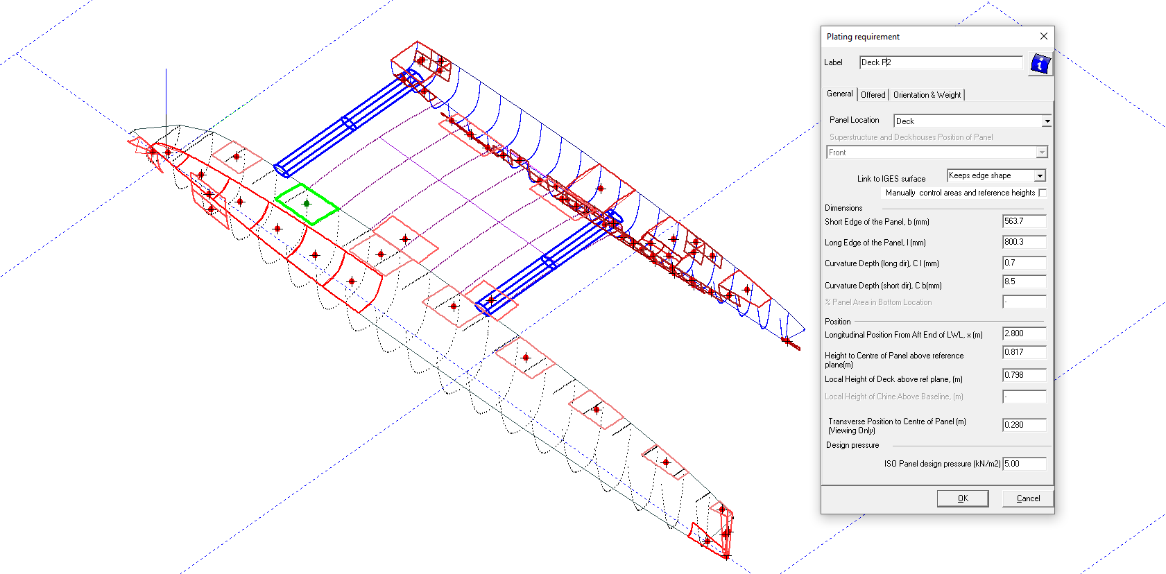
I want to change the vertical location of a panel, but its fixed
If you have imported the panel (or stiffener) as an IGES surface (or curve respectively) the default setting is to keep the shape as per the original IGES entity, with the height and area etc derived from this shape / perimeter definition. If the shape / size is to be kept , and you just want to move the panel vertically then click on the checkbox near the top of the panel dialog, listed as ‘Manually control areas and reference heights’. This will let the user change a number of parameters, but NOT the panels length, width or curvature. If you want to completely discard all links to the original IGES, then check the ‘manually control heights’ checkbox as above AND change the pull down options (listed as Link to IGES surface) to “No Link”. Be aware that if you reset the ‘link’ you can’t go back (ie it’s a one way process, as the surface information has been discarded), thus saving your work before doing so is a prudent action.


More information : There are 3 level’s of linking to an IGES entity in Hullscant : 1) a full link to the entity where the panel shape & location is recalculated from the IGES (which is saved alongside the Hullscant file) whenever it is loaded, 2) a storing of the IGES’ discretisised shape , but NOT the underlying mathematical NURBS definition and 3) no link where the IGES shape is read and converted into a length, width and position, and then all knowledge of the IGES surface is discarded. The default is level 2, where the IGES is converted to a discrete shape and that information is stored, allowing the user to move the shape around and manipulate it without storing the underlying mathematical definition nor have to convert it to an equivalent panel each time.
I’ve imported a panel, but the shape does not look correct
HullScant converts the true surface shape imported from the IGES file first into a 4 sided shape and then into an equivalent rectangular panel (ie length x breadth, with curvature Cl & Cb). The selection of the ‘corners’ of the 4 sided shape is determined by the change in direction as the perimeter of the surface is traced around. For some compex shapes Hullscant can chose poorly, so there is the option for the user to alter the corners. In the panel dialog, ‘Orientation & weight’ tabsheet, chick on the ‘Edit corner location’ button, and the resultant dialog will let the user move the corners –

Use the arrow buttons to shift the chosen corner around the edge of the IGES surface. The equivalent ISO panel is shown as a dotted red line.
I’ve imported a panel as IGES but cant change its size
Any IGES imported panel has its length, width, longitudinal position and curvature set according to the IGES surface. If the user wants to change any of these, then the ‘link’ to the IGES shape needs to be removed. This can be done by clicking on the ‘Link to IGES’ pull down in the panel dialog, and settins it to ‘No link’. The user can then edit the length, curvature etc edit boxes.
Material Properties
When I load a release 1 file into release 2, the material properties have changed
R2 > The 12215-5:2019 ISO standard has significantly different material properties for FRP’s compared to the 2008/2014 standard. Note that a few metal properties (Al alloys in particular) have changed also. The 12215-5:2019 ISO standard does not have any core material properties listed, hence the data from 2008 has been used but these properties are known to be very conservative in comparison to manufacturers data sheets. In addition , 12215-5:2008/2014 used evaluation level A/B/C, which (in the case of level C) would lower material strength and modulus by a factor of 0.8. 12215-5:2019 does not use evaluation level, but does use Kbb & Kam (1 to 0.75 & 0.95 to 0.9 respectively) on the material strength (not modulus).
When I define material in the Material library, the program shows me the material properties. But in the data sheet of material I have much different values. Which is correct?
R1 > The values pre-defined in HullScant are those ‘approved’ and selected within the ISO 12215 standard. Actual material values will clearly vary according to manufacturing process, base materials, quality assurance etc. The ISO materials can be seen as the ‘average’ material, and there will be a great number of more specialised materials with higher strength or modulus, etc. There is also the underlying reason that the ISO values are relatively conservative, due to the requirement that they cover the materials produced by all manufacturers, as they can be used (via evaluation level c) without any material test data checks. You have the ability to enter your own materials into the database (and indeed, racing yacht designers do so regularly) by adding (‘Test Data Material’) to the materials database. Be aware though that there are separate rules and regulations covering a structure where you are using manufacturers test data properties rather than the default ISO values; The Wolfson Unit strongly advise reading Annex C of ISO 12215 part 5 (and any other associated Annex) before using test data values in your structural assessment.

In the boat particulars dialogue should I be using EL-b, measured fibre content by mass, or EL-c, ISO fibre content by mass? The latter gives a lower strength result.
R1 > If there is no explicit test data for the material then it should be EL-c. This is clearly described in Table C.1 of the ISO 12215-5 standard. There is a 0.8 factor on all mechanical properties calculated on the standard where there is not explicit actual measurement of the fibre content.
I’ve observed inequalities in the material property calculation between the ISO standard 12215-5 and the presented solutions in the HullScant application. The presented values are only 80% of the default values coming from the ISO standard. Why is this?
R1 > The default setting for the material properties are specified to be the “default data (Tables C.4 to C.7) with a multiplication factor of 0.8”, as per evaluation level EL-c , specified in Annex C, C.1.1, General. Therefore you are correct to state that the values are 0.8 of the values specified. If you want to use EL-b (default data), select the required value in the boat particulars dialog. Be aware of the implications of the different evaluation levels and their requirement for quality assurance checks.
R2 > In the 12215-5:2019 standard the evaluation level has been removed, but a boat building factor (Kbb) and assessment method factor (Kam) have been added, which range from 0.75-1.0 and 0.9 – 1.0 respectively, and can have a different combined value within the same structural assessment according to material type and manufacturing method.
HullScant does not seem to calculate carbon properly. If, for this boat, I insert a glass laminate with the same weight as one of the tested carbon laminates and check ‘Calculate’, the glass layup will pass but the carbon layup will fail – at the same weights. The carbon needs to be significantly beefier and heavier than the glass laminate in order to pass!
R1 & R2 > Check what orientation you have the carbon in. The material properties are determined in accordance with ISO (annex C, Table C.5 in particular). For example, double bias (DB) properties are very low in tensile and compressive strength. If for example you switched the outer layer (both inner and outer skins) to woven roving (300g/m) instead of DB (300) then the panels pass.
IF the NA is close-ish to the crown AND you have any 90 UD’s (by which I mean UD running perpendicular to stiffener axis) AND you’ve entered this as an individual ply then HullScant will home in on its poor tensile failure strain of 0.45% or there abouts. It’s a FPF (first ply failure) method. If you have got this, try deleting these plies – if this is the problem then the M_offered will increase massively as the increase in limiting strain massively outweighs the minor loss in EI. This is why I model the inner skin/outer skin as two individual plies. My motto – never let HullScant see a 90 deg UD in tension!
Does EL c also take into account that the higher resin content inferred by the 0.8 factor would create a slightly thicker laminate?
R1 > The laminate thickness is the same as ISO data; only the material mechanical properties are altered (down to 0.8). This is an additional safety factor and the reduction in mechanical properties does not infer different resin content than the default values.
In the Material Library, when adding a GRP Multiple Laminate, what does “Multiplied or Crossplied Fabric” mean exactly? Is it a double axial 0/90° stitched fabric, a quadriaxial +/-45°/0/90° stitched fabric or still something else?
R1 > Multi or Crossplied fabric refers to bi-axial (0/90) fabric. If you need in the future to apply a double bias (+/-45) or quadriaxial fabric, you will need to add the material in the material library from: {Material Library => Add =>GRP Laminate} and then build your layup in the laminate library.
What is the difference between biaxial, double bias and multidirectional fabric? They are all unidirectional fibres that lay on top of each other in different angles and are stitched together. Am I mistaken?
R2> Double bias is +-45 degrees, Bi axial is +-90 degrees, as per the ISO standards naming convention (eg Table C 5) . When adding materials into the library from the ISO database, the material name should reflect the fibre angle
R1> Double bias is +-45 degrees, Multidirectional (Crossplied) is +-90 degrees.
Note : You should not use DB or Quadraxial cloth in the “multiple laminate” because these have quite different properties from the more basic CSM, WR etc. where these are treated as a homogenous material with a thickness. Therefore you have to use laminate analysis for these.
In the Panel Results, what is the second column? Is it the minimum requested thickness or the minimal dry fibre weight as defined in 10.6.2 for FRP. The results don’t quite tally with what I expect them to be.
R1 > For FRP single skin panels HullScant calculates the equivalent required thickness from the dry fibre weight specified in ISO12215-5 Part 10.6.2 and examines this against the actual thickness. So HullScant does compare thickness against thickness. Check that you are not using a ‘laminate’ sandwich. You should be using a “Multiple GRP laminate” via the materials library (these (single skin & sandwich) are assessed in different ways.
I would like to use Coremat type materials in the webs of some stiffeners to increase web stability. If I use “add>>core material” in the materials Library window, there is no option for this type of material. If I insert it as one of the options show or as a test data material there is no option that makes it work as a material that increases shear web stability. Do you have a workaround for this?
R2> Read the answer for R1 below (it has the background details and concepts), but in addition, the new standard allows flexural strength to be used (for single skin only, not sandwich structures), so the used does not have to make test material with the compressive/tensile strengths overwritten as per R1, but coremat does still need to be classed as a Laminated Ply (if it was classed as a core then it would be assessed as a sandwich ). The download at the end is a R2 file.
R1 > Coremat thick is typically only half of total thickness of laminate and E value is much higher than real cores. This means treatment as a ‘thin’ sandwich (i.e. make as laminate in HullScant) is probably not correct. It is probably only ever used with CSM & WR which means normally the user would model panel as a multiple GRP laminate (i.e. a material). This uses flexural properties, not in plane. For example if you make up a multiple GRP material (see “6 x CSM MATERIAL” in the Materials dialog below) which gives a thickness compliance factor of 1.058. If the same 6 plies of CSM600 are modelled as a sandwich then it fails. This is because ISO defaults to in-plane properties for sandwich and UTS CSM < UFS. The problem is therefore how you get the laminate to use flexure properties, not in plane.
Define the Coremat as a material (‘Test Data’); It is probably best not to model COREMAT as a core material; use E glass instead, entering the relevant material properties (see screen grab below). Next add the other plies used (CSM, WR) as ‘Test Data’ as well, using flexural properties only the user can then build a laminate with Coremat in.
Finally, it might be worth doing a manual shear strength check at the neutral axis.


An example Laminate:

Some example files can be downloaded here:
I am adding materials to the material library. I am stuck as to how to add Soric flexible core. I can’t add it as a core because none of the choices in the drop down menu are even close, and I have the same problem trying to add it as a reinforcement. Do I add it as a “test data material”?
R1 > Entering the information as test data is the correct approach, but this isn’t going to be that straightforward…….
If you treat it a sandwich (i.e. SORIC entered as a core in test data) HullScant will recognise it as a core and will employ thin sandwich theory as per ISO. The core will have a zero E value and the program will do both a core shear strength and EI check in addition to BM check. This is wrong. The E value of the SORIC is much, much higher than a normal marine core AND these aren’t really cores but ‘bulkers’ and are typically 2-4mm thick so thin sandwich approach is violated.
The best way to deal with this type of product is to treat it as a single skin (but using the laminate stack Annex H) – i.e. SORIC is entered as a laminate in test data. Without the magic word, ‘core’ HullScant will treat as any other ply and include the SORIC E value. BUT it won’t however do a shear or EI check.
Recommendation: Treat as single skin. If it is just 2-4mm thick bulker the SF and stiffness are probably not going to be a problem. If they are thought to be so then you will need to model it as a sandwich AS WELL or do a manual check. Finally, if entering as a core (as a 2nd check), make sure shear elongation (<35% or 35%) is correct for the material – work out USS/G from the type approval certificate.
In your choice of core material what is the difference between PVC I and PVC II? Both are listed as cross linked.
R1 > There are three broad classifications for rigid PVC compounds: Type I, Type II, and CPVC. Type II varies from Type I due to greater impact values, but lower chemical resistance. CPVC has greater high temperature resistance. You should match manufacturer’s data to the type set in HullScant. Typically most would be Type I.
I’ve used Quadraxial ply as a single skin, with the results giving a 0 required thickness and failing. When I looked closer at the results, quad (and UDWR) shows zero for flexural strength in the material properties. Why is this?
R1 > This data is derived from Table C.7. There is no ability to derive flexural strength from this table and members of the Working Group suggest that only actual test data should be used for flexural as it is very difficult to predict. If you convert this to a Laminate then you can get an answer out of HullScant (laminates use in plane strengths whereas single ply constructs use flexural). It is clear that HullScant is quite conservative when a single ply is used as a laminate. So two solutions… Use a laminate instead of single ply and increase the material to comply. Or get some test flexural data for the Quadraxial material and add this material as a “Test Data Material” in the Materials dialog using the other properties derived from ISO 12215-5.
Laminates
I’m getting a different minimum BM shown in the laminate dialog in Hullscant R2 compared to R1. I opened the R1 file, and made sure the material properties were kept the same, so why the different BM ?
For single skin laminates (ie no core), the 2019 standard allows the use of flexure strength ( C.2.3), whereas the 2008/2014 standard did not recommend it , hence Hullscant R1 always used compressive / tensile strength for FRP panels. Hullscant R2 uses flexural strength for single skin, & tensile / compressive strength for sandwich structures.
Most of the internal/ ISO FRP materials in Hullscant R1 did not have a flexural strength listed (follow on from point above), hence if importing and NOT updating material properties, one would need to add a flexural strength (there is a suggested formula in 2019, C.2.3).
By 2008 standard (and Hullscant R1), safety factor on material strength was 0.5 (with evaluation level possible also lowering strength AND modulus by 20%). By 2019 standard (Hullscant R2), safety factor is still 0.5 (table 17), but one also has Kbb (1.0 for test materials, 0.75 for low) and Kam (0.95 for enhanced, 0.9 for simplified)
Hence even best comparison of R1 v R2 Hullscant is going to have a 0.95 ratio on the design strength , which is the case with –
- In Hullscant R1 set evaluation level as A, add a material (eg carbon WR 200g/m2), and make a laminate of 2 layers. In this case the min BM is listed as 2.46 with an EI of 243.07
- Save, and load in Hullscant R2, being careful to keep material properties rather than updating them.
- Open the material properties and set the flexural strength to the lower of compressive & tensile (which is what was being used in Hullscant R1). For carbon WR this is compressive, 56.7
- Set Assessment method to enhanced (so Kam =0.95). Kbb will equal 1 as the material has been classified as test data.
- Open the laminate, EI is 243.07 (ie same as in Hullscant R1) . Min BM is 2.34 (ie 0.95 of equivalent in Hullscant R1) . If assessment method is left as simplified, then the min BM is 2.22, 0.9 times the Hullscant R1 value.
When you create the material stack is the gel coat side at the top or bottom of the list, and does it make any difference anyway?
A laminate is created as if laying onto a female mould with the outer most ply first and inner most ply last. This applies to a schedule made using the laminate option. Using the multiple GRP material option it doesn’t matter (If you try the up/down buttons and check say flexural strength (which is the key property here) nothing changes). However, for best practise do it in the order of laying down (and the Wolfson Unit would tend to specify each individual ply rather than lump them together) is for audit purposes and so as not to confuse the builder in the unlikely event he needs to see the HullScant output.
I’ve got a CSM layup (which I was using as ‘single skin’ in Hullscant), but when I converted to using a laminate stack and added some WR, it starts to fail. What’s going on?
R1 > IN GENERAL: When you use the laminate option 12215-5 uses in-plane properties. The UTS of a CSM is about 68-80 MPa. When you use a MATERIAL stack (only available for CSM/WR/BX plies) it uses the Flexural strength – more like 130 MPa. Hence the different answers. The flexural strength is probably more correct for GRP single skin but data not so available for complex laminates hence LAMINATE option. Good for sandwich but for clever layups the user really should test the material properties. So if you have a WR/CSM/BX in roughly alternating plies or at least evenly distributed, use MATERIAL method and only use a laminate stack for cored layups
Back to the case in point: If you turn on stress ratios in results, and look at your hand lay bottom laminate, the problem is the WR ply in compression. This is due to the low failure strain of WR compared with CSM.
I have created 2 different laminates, and used them alternatively for the same stiffener. However the stronger laminate is failing in HullScant, whereas the weaker one passes. What’s happening?
R1 > The stronger laminate (which fails according to HullScant)-

The weaker laminate –

HullScant/ISO-12215-5 is a first ply to fail method (FPF). This means if a ply is introduced which has a much lower failure strain than any other of the plies, it will generally be that ply that triggers failure. This is what happens whenever a 90 degree UD is introduced as is the case for the panel with 195gsm 90 deg ply. When this is used in a stiffener as attached plating, the attached plate is in tension (12215 assumes built- in ends). The tensile failure strain in the 90 deg ply is about 0.5% whereas it is nearly 2% in the other plies, so the 90 ply triggers failure.
Sometimes it is possible to get away with this but if as in this case the weight of crown UD’s moves the neutral axis well away from the plate then the problem is compounded. Simply by deleting the two 90 plies from the laminate, the stiffener S1 one part becomes stronger (i.e. about the 14.3 kN.m given in the passing file). The same thing happens when you use aramid (unless you use a lot of it).
I’m considering using “Strongplank” material. What is the best way to model it in HullScant, particularly the “webs” in terms of cross linking the plies. Test data is a bit sparse. How can the cross linking of the skins that comes with Strongplank betaken into account?
R1 > The laminate analysis method assumes there is a bond between the skins and core. It would be necessary to input this as a material from test results to be sure. It should be analysed as a laminate for the purposes of the program.
If you have test data, and the shear properties are for the complete structure, then I would enter the properties as specified, and view the structure as one entity, i.e. skins included with the Strongplank ‘core’.
It is understood this is a composite style strip-plank, i.e. used for hull, with the inner and outer faces glassed over with epoxy. Assuming that the radiused edges get filled with epoxy AND a top-notch secondary bond is produced, structurally we would have:
1. Outer and inner skin = horizontal flanges of Strongplank plus sheathing.
2. ‘Core’ material consisting of actual PVC core (assuming this has a decent density and it therefore structural) plus the vertical web.
It is suggested that a single pseudo-core having the actual thickness of the PVC be created but with properties derived as follows:
a) Calculate minimum strain from web and core (probably the GRP component)
b) Calculate the E value (or G value for shear) using:
G(effective) = (2 x tweb x Gweb + width PVC x G PVC)/(2 tweb + width PVC)
c) Calculate USS from G effective x min strain.
The actual laid up inner and outer skins should then be added to the laminate, but not the strong plank skins as they are already accounted for in the ‘Strongplank’ core.
I have a wooden yacht construction which is a combination of plank on frame, but with a double veneer of cold moulding over the top. Is this catered for in the program? I can see how to use normal plank on frame, and also full cold moulding, but not the combined.
R1 > First thing first – it is best to start reading all of Annex E!
There are two possible methods. The first is an Annex H laminate stack. You need to set up two offered panels, one //, one #, corresponding to with or across the grain. This is a more conservative but more scientific method. It is very dependent in panel AR and it is suggested to use # to the grain. The Wolfson Unit suggest you set up wood # to grain yourself to see what’s going on. The alternative method is to treat the whole stack as a pseudo single material. Handle with care! See the attached BST file for examples of both of these methods.
General hints & helpers in the use of HullScant
1. Avoid UD’s for panels in HullScant – this is a first ply to failure method and not a laminate analysis program – always try to combine a multidirectional ply using the closest possible combination of WR, DB and QX
2. If UD’s must be modelled (and this will mostly give lower strengths) then it is necessary to use the option to produce a 90 deg laminate (option available in the laminate toolbar – this automatically creates a second laminate at 90 degrees where UD0’s become UD90’s and vice versa. QX/BX/WR/DB are unaffected) and within the second tab of the panel layup offer this new laminate in the long direction.
3. A much better approach is to use the material library option of defining test material and calculate the properties of the single ply in both directions using CLT (outside the scope of HullScant) but avoiding the ply by ply trap. This avoids the problem – even a BX (same strain in two principal directions) always comes out better that a two ply layup of one UD0 and one UD90. E’s are the same – strengths are different.
R1 > 4. Even better – use test data – not a lot of point going to the trouble of vacuum bagging only to use EL-C or even B really.
Panels
What are the various abbreviations (e.g. Wos)?
R1 >
Wos = outer skin weight
Wis = inner skin weight
EI b is as per equation 42 of the standard, combining 2nd moment of area with modulus. The subscript b indicates in the shorter direction (see BML & BMb for corresponding bending moment values for long & short directions).
In the panel requirements dialog screen, what is meant by “The % panel area in bottom location specifies the percentage of an area of a side panel that extends into the bottom”?
R1 > The answer to your question is based on section 6.2 of the ISO 12215 – Part 5. The input you are required to enter into HullScant is the area of a side panel (for the hull) that extends to the bottom, in percentage term. For example, if your panel area is 100% above the waterline, then this value is 0% (i.e. a side panel). If, say 70% of the panel area is above the waterline and 30% of it is below, then the value to enter is 30% (i.e. a side panel that extends to the bottom of the hull). If the panel area is 100% below the waterline, then this is defined as a bottom panel in the dialog.
The K2 and K3 (aspect ratio) coefficients don’t appear to be correct comparing against table 5 in 12215-5:2008. With an aspect ratio of 1.67 the K2 & K3 values must lie between 0.468 / 0.476 and 0.025 / 0.026 respectively, but HullScant is providing much smaller values.
R1 > Check if you are using different material properties in the short direction as opposed to the long direction. Table 5 is for isotropic panels. For an orthotropic panel the function to Calculate K2 & K3 gets passed the effective aspect ratio based on the stiffness:
Effective aspect ratio, EAR:=(Length/spacing)*power(DS/DL,0.25), where DS:=short laminate EI, DL:=long laminate EI
This EAR is then directly used in the calculation of K2 & K3. Hence the different factors
This is as per Annex H.2.1.12, & table H.3
But ….Effective Aspect Ratio is only used in the calculation of alpha, beta b and beta l, and therefore in the calculation of Mdb (maximum design bending moment in the b direction, Nmm/mm), Mdl (maximum design bending moment in the l direction, Nmm/mm) and y/b (maximum relative deflection, mm/mm) for orthotropic panel calculations at Annex H (normative). It is never used in the calculation of K2 or K3, even if in the standard Table 5 is clearly indicated to be used for isotropic panels because orthotropic panels don’t use it.
R1 > Table H.3, α and βb equations are curve fits to K2 and K3 as may be found in ABS guides. To convert from α to K3 multiply by 12. To convert from βb to K2 multiply by 6. Hence as high aspect ratio, α= 0.00237 or 0.028 as K3 and βb = 0.0833 or 0.5 as K2. This a minor difference, as in Table 5, the original Timoshenko coefficients were plotted on a more complicated basis. This is all true for AR or EAR. It was decided within HullScant to use α= K3/12 and βb= K2/6 in order to avoid minor differences when analysing either using Annex H or main body of the standard. The difference is trivial but might have caused some confusion with users. The equations in H.3 were checked against FE plate models to check their validity and also to develop βl. There is no main body equation equivalent to βl so this is programmed as per Table H.3. The FE plate models apply to especially orthotropic layups (e.g. plywood). DO NOT USE FOR COMPLEX ANGLE, NON-SYMMETRICAL LAYUPS – USE CLASSICAL LAMINATE THEORY (CLT). The presumption is that the stiffest direction is parallel to the short side as this is the logical way to layup a panel (having said that the equation will cope with minor (only minor) deviations from this presumption). As such by laying up the stiffest material in short direction, EAR > AR. This makes sense as the panel is receiving less support from the long direction and so the panel more nearly corresponds to ‘cylindrical bending’ for which transverse strain is zero.
General hints & helper
R1 > The user doesn’t need to check the panel in both directions (short side and long side) in panel requirements if your laminates are CSM/WR. You only need to do this if you have a different offered material in that direction (e.g. 90 degrees to a unidirectional or a bias fabric).
Stiffeners
I’m getting a significantly different ‘offered SF’ in R2 when compared against R1 (eg 55% !) . I imported the R1 file into R2, and didn’t change anything.
R2> See also 5.17 below for more detail but for background information the method of calculating shear stress and offered BM is different in R2 compared to R1. This in itself should only make a small difference (probably < 5% ). The underlying reason for big differences in offered SF (and BM at times) is the change to material properties according to the ISO approved values as well as the boat building factor (Kbb) and the assessment method factor (Kam). For example , take a multiply of CSM & WR. In R2 the material properties dialog shows the shear strength to be 42.91 N/mm2. In R1 it is 54.03 N/mm2 (including evaluation level C). For FRP, Kam is 0.95. If a boat building level of LOW is used (Kbb = 0.75) the shear strength in R2 then becomes 42.91 x 0.95 x 0.75 = 30.57 N/mm2 . That is, 56 % of that in R1. This then cascades thru into the offered shear force.


The Results report shows a bending moment. Is that the maximum value that the stiffener can support?
R1 > Yes the ‘offered BM’ is the greatest BM the stiffener can support using the safety factors on materials as per the ISO standard.
Transverse and longitudinal stiffeners: do I have to specify a stiffener length as the gap between the crossing bonds ?
R1 > It depends on the stiffener and what it is expected to support. Usually transverse stiffeners are fully supporting the panels either side. Refer to Section 9.2. of ISO12215:5
Scantling bulkheads: do I have to input a bulkhead as a beam, divide it into longitudinal frames, and define it with the local height ?
R1 > Yes this is the method required. Refer to Section 9.2 of ISO12215:5
In the calculation result for stiffeners, is the “offered” values for the stiffeners base on exact values of section modulus or values from table in Annex G?
R1 > The section modulus for stiffeners is calculated from first principles, not interpolated or derived from the tables of Annex G.
R2 > As with R1, the section modulus is calculated from first principles
Is the effective plate width automatically adjusted if the stiffener spacing is less than that width?
R1 > If the stiffener is set up as a hybrid/laminate stiffener it will adjust the plating size accordingly and automatically. If the stiffener is set up as a complex stiffener then the plating size must be set in the stiffener builder. It will use this size to calculate mechanical properties.
Our current design has a large webframe without any longitudinal framing in the area of interest. Hence some of the stiffener is below the water line and some above. If I enter this as a bottom web, HullScant finds a design pressure of 20.5 kN/m2. If I calculate it as a combined bottom/side web, HullScant gives a design pressure of (only) 10.5 kN/m2.I also calculated it as a side web, and HullScant also gives 10.5 kN/m2.
In other words, it appears that HullScant assumes that most of the web is above the waterline, while in fact it is for more than 2/3 under the waterline.
R1 > What’s happened is the % of frame in the bottom zone has been set to zero (see highlighted input parameter in dialog box below). So HullScant thinks it’s all in the side shell zone and gives a 100% side shell pressure. If you enter a figure of 80% in the bottom zone in the amended input, then Hullscant calculates according to part 5, 6.2.5. As the minimums govern, 10.5 kPa (side) and 20.5 kPa (bottom), HS calculates pressure as 0.2 x 10.5 + 0.8 x 20.5 = 18.5 kPa.

As I read the rule, if a bulkhead does not meet the structural requirements for a water tight bulkhead, it can be regarded as a stiffener. However, as I read it, you can only regard the bulkhead as a stiffener with a height of 7 time its thickness. In other words, it we have a bulkhead from 12mm plywood, it only counts as a stiffener 84mm high?
R1 > Not quite, no. A structural non-watertight bulkhead is handled under 7D (D = depth of hull in metres), as defined in Section 11.8.1 of the standard. The thickness of the bulkhead cannot be less than 7 times the depth of the hull in that area. See also the comments from a member of the working group to the question below.
I didn’t see anything regarding the definition of non-watertight structural bulkheads, wood or sandwich (ref ISO12215-5 chap 11.8), in Hullscant. How are these accounted for?
R1 > Structure that is not classified as a bulkhead but provides structural support can be viewed as a stiffener (ISO 12215 part 6 is probably worth re-reading). Table 20 (sect 11.7.2) limits the height to thickness ratio (h/tw) to 10 for a flat bar plywood stiffener (thereby giving 120mm height for a 12mm ply structure).It is also worth reading section 11.8 of the standard.
And some words of wisdom from a member of the ISO 12215 working part – “a structural non-watertight bulkhead is handled under 7D (D = depth of hull in metres). It’s a semi-empirical equation, with some simple plate theory behind it, but not much. If you wish to analyse a ply or cored bulkhead as a stiffener, I believe that this should only be done in the case of cut-outs which produce a beam-like ‘transverse frame’, i.e. the span/depth > 5. If this is the case then the dw/tw limits (to prevent shear buckling under in plane bending) become meaningful. I wouldn’t try to analyse a deep ply bulkhead by just considering an artificial depth based on 12t or similar. An in-plane stress analysis of a deep bulkhead is not practical using simple equations. The 7D seems from experience to give adequate racking stiffness so I’d leave it at that. There have been various efforts to develop an equivalent stiffener but these predate the 7D.”
What is the best way of defining full height longitudinals and bulkheads i.e. those which are attached to both the hull and deck? At the moment I am treating them as a “T” type, but this poses the question of how much inner plate to use. What is the usual method?
R1 > If the vessel is a small boat feature such as a RIB where the depth between bottom shell and deck is sufficiently small that the ‘web’ is attached to both deck and bottom so as to make an I-beam, then we then have an I-beam under deck pressure and bottom pressure. There are a number of issues here, some 12215-5, some HullScant. The approach is to make a complex stiffener, i.e. manually enter the effective deck plating at 20 (t_i+t_o) deck + presumably cored web thickness and likewise for the bottom shell. It is probably best to treat this as bottom stiffener as this gives the largest pressure. HullScant will then give you the compliance factors.
However, there are a few other things to consider. The first is web buckling. Assuming a not untypical couple of plies either side of a H80, 20-30mm core, the ISO slenderness limits (based on ‘hollow/PU’ cores, albeit with a shear force compliance factor >>1) may need some additional investigation outside HullScant.
In the past, faced with these it is sometimes better to use an ‘artificial’ span since if you have a series of full-deck transverses and girders (i.e. egg-box style – see ISO-12215-6) you can’t be sure what’s supporting what. As the beam theory only really works for span/depth > 5, the user might also treat a floor web as an unstiffened WT bulkhead (even though it’s not designed as such) since for a typical small boat head of 0.5-0.7m it ought to be able to survive no problem. Of course if this is a RIB or similar then the floor design point (built-in) is at the shallow ends under ISO – this might be a problem – one option might be to treat as simply supported and look for a minimum CF at the keel of 1.5 in bending from HS (assumption depends on deadrise). However you still have to model the shallow depth at the deck extremes for shear and this could be a problem. A detailed analysis of this is beyond the scope of Hullscant and this FAQ; the user should speak to a structural engineer with a knowledge of the standard, relevant small craft structures and the requirements of the notify body.
For topside stiffeners, is there anywhere were the neutral axis for the top-hat-stiffener/hull-flange combination can be seen?
R1 > You should be getting this shown as a black dotted line in the laminate view window, as shown below.

When creating a stiffener can I insert pad layers (inner-skin reinforcements) separately form the hull laminate, or of width other than the hull plating effective width?
R1 > Yes, just insert layers in. Remember you will need to do this as a ‘complex’ laminate, rather than the standard off the shelf top hat etc.
Table 21 shows the value of Table 20 being multiplied by the square root of the actual BM over the BM design (hopefully less than unity). This then further increases the minimum thickness required for a given web or crown dimension which seems strange – is this correct or have I misunderstood the standard?
R1 > Ksm and Kas cannot be less than 1.0. They are the ratio of the offered value to the required value. So if you have more section modulus than required then KSM > 1 and so the applied compressive stress in the flange will be lower. This means dividing by the 1% ultimate strain is making the flange unnecessarily stiff, hence the root Ksm factor.
Hullscant doesn’t appear to evaluate the slenderness ratios of stiffener web & flanges in much rigor. Also using a value of 35 for carbon laminates (Table 20) is a bit of an assumption since for basic GRP – covering the majority of craft – the value is 30 for webs and 21 for flange. What is the reasoning behind all this?
R1 > The crown slenderness ratio is loosely based on the Euler plate buckling equation which for an isotropic material is 3.62 E(tf/d)^2 where t = thickness and b = width of crown. The requirement is for this stress to be (roughly) twice the applied stress. It is easier to write this in terms of strain so: d/tf = (3.62 /(2 x 0.5 ultimate strain))^0.5 (Note 0.5 is the allowable stress factor, and this is valid when the BM or SM compliance factor is 1.0000)
For GRP the ultimate strain in compression varies a lot between CSM and WR but using 1%, this equation would yield (3.62 /(2*0.5 x 0.01))^0.5 = 19 (NOTE for all CSM using this logic, the factor would be more like 14). The figure of 21 is the ABS figure – it is in line with the above derivation (which was used for all the other materials) and 21 was kept to give agreement with ABS (ISO 12215 pt 5 tried to look a bit like ABS ORY).
Coming up with a slenderness for the web is even more difficult. The web is actually under combined in plane bending and shear. This requires a quadratic interaction equation which is too complex for use in a simple rule formula. The web limit is loosely based on shear stress only (and some comparisons with existing rules).
In addition, the methods assume a totally non-effective former. Even with a PU32 it is not certain if this behaves exactly the same as a genuine hollow pre-moulded/bogged down stiffener. For a 80 kg/m3 core, the slenderness ratios are probably meaningless. Also, many crowns have UD’s (sometimes carbon UD300) with glass over bonding. This is not only a mixture of two different materials but the orthotropic buckling equations are different from the isotropic ones.
No simple rule can do everything!
So because of the uncertainties, it was decided that the check should be a ‘yellow box’ warning only. Many RIBS have very tall thin webs and it would be misleading if Hullscant was showing failures when these aren’t happening in practice.
Finally, remember that ISO-12215-5 is one of a number of methods permitted under Recreational Craft Sectoral Group (RSG) guidelines.
Can I be sure the Offered Bending Stiffeness from the HullScant Report is correct ?
R1 > HullScant has been validated over a number of reference cases. Based on examplemotoryacht.bst (reference case which comes with the installation package), here is a detailed calculation for the “Deck Stiffener 1″/”Coachroof Stringer” attached to the “Coachroof Sandwich” laminate.
The calculation was performed based on ISO Standard 12215-5 chapter 11.
(In addition to the following, a worked example can also be found in Annex H which contains the full analysis for a Top Hat stiffener)


General hints & helpers
R1 > Effective width: The 20 (ti+to) (from LR SSC) really hits thin skinned cored panels with typically 20-30mm NOMEX ‘former’ L’s. This is big reduction from the ABS ORY equivalent ‘t’ .
If struggling to understand why the stiffener is failing
a), create it using the hybrid method – make a copy and then convert – this gives a nice graphic showing position of NA. Makes it easy to see how highly loaded the plate v crown is and allows simply deletion/editing – it is also necessary for b) below.
b) If all else fails and only thing left is to pull NA closer to plate – insert ‘pad’ of typically 200-300mm wide 3/4 plies of EUD0 under stiffener and over inner skin.
Is the calculation method for EI, BM , SF etc for the offerered stiffener the same in R2 as R1?
R2 > As with R1, all properties are calculated from first principles. In general the same method is used except for the offered SF. In R1 the sum of the shear modulus area of the web multiplied by the strain at design stress determines the allowed shear stress and hence allowed shear force. In R2 the shear flow method, as presented in Annex H, is used for the enhanced method and the same approach as R1 for the simplifed method (where required) . Validation studies have shown the two methods to generally have the same answers , and usually within 5% of each other.
The stiffener report shows the offered bending moment (BM) and shear force (SF) with and without the Kbb and Kam factors, but the ratio between the BM and SF changes from stiffener to stiffener, AND it is not always the same ratio for BM as for the SF. Whats going on ?
The Kbb factor ranges from 1.0 to 0.75 , depending upon type of material, layup (in case of FRP) and the build quality. The Kam factor ranges from 1.0 to 0.9, depending on material and assessment method.
Example Stiffener A) Made using hand layup FRP, assessed by simplified method. The BM with factors is 0.855 of the value of the BM with Kam=1 & Kbb=1, as is the SF => Kam is 0.9 (simplified assessment of FRP) and Kbb is 0.95 (hand lay up, high quality). 0.9 *0.95 = 0.855
Example Stiiffener B) Made using FRP, stiffener is built with resin infused former, attached plating has layers of hand layup; using simplified method. The BM ratio is 0.855 but the SF ratio is 0.9. The shear force offered is being controlled by the web, which is resin infused FRP (Kam=0.9, Kbb=1.0 =>0.9), but the BM could either be the flange of the web OR the attached plating . In this case it is the attached plating (Kam=0.9, Kbb=0.95 => 0.855)
Example Stiffener C) Same setup as example stiffener B, and SF ratio is still 0.9, but BM ratio is 0.864 ! What is most likely here is that the critical layer for the BM has switched from the tension ply (attached plating, Kbb=0.95) to the compression ply (flange of stiffener, Kbb=1.0) , at which point the exact compressive and tensile strengths, and their ratio comes into play and a non-intuative ratio can occur.
Help and support
If you need any support from our team for the effective use of our software, please get in touch.